| Switch 1: |
| OFF: |
Normal setting |
| ON: |
Continuously perform the Power-On Self Test (POST) |
|
• ON: 'Test Chamber' mode - see here. |
| Switch 2: |
| OFF: |
8087 math co-processor chip is installed |
| ON: |
8087 math co-processor chip is not installed |
|
• 8087 sits in IC socket U4, adjacent to power connectors. |
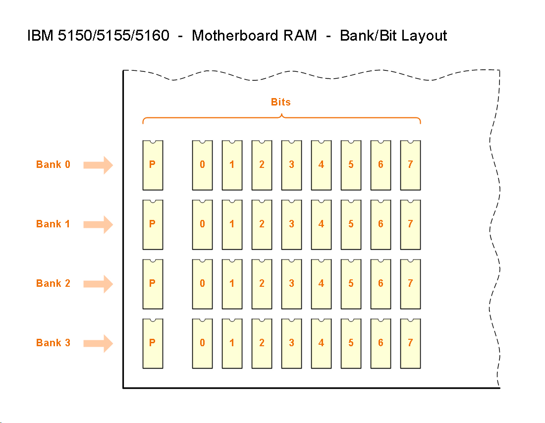
| Switches 3 and 4: |
Enabled motherboard RAM.
| 3=ON , 4=ON : |
Enable only bank 0 |
| 3=OFF, 4=ON : |
Enable only banks 0/1 |
| 3=ON , 4=OFF: |
Enable only banks 0/1/2 |
| 3=OFF, 4=OFF: |
Enable banks 0/1/2/3 |
|
• Click here to see a diagram that shows the four RAM banks. |
| Switches 5 and 6: |
Video card type.
| 5=OFF, 6=OFF: |
MDA (monochrome) |
| 5=OFF, 6=ON : |
CGA, at 40 column by 25 line mode |
| 5=ON , 6=OFF: |
CGA, at 80 column by 25 line mode |
| 5=ON , 6=ON : |
Cards with a BIOS expansion ROM (e.g. EGA / VGA) |
|
• Assumption: Only one video card fitted.
• For VGA card compatibility, click here.
• For PGC cards, see here. |
| Switches 7 and 8: |
Floppy drive count.
| 7=ON , 8=ON : |
One floppy drive |
| 7=OFF, 8=ON : |
Two floppy drives |
| 7=ON , 8=OFF: |
Three floppy drives |
| 7=OFF, 8=OFF: |
Four floppy drives |
|
• The IBM 5.25" Diskette Drive Adapter supports double density drives only. |